STUB ENDS ASME AND MSS FOR PIPELINES
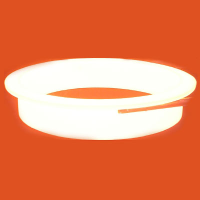
DEFINITION
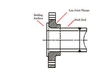
Stub ends are mechanical joints that comprises of two components:
- The Stub End, which essentially a short length of pipe, which has one end that is flared outwards and the other end prepared to be welded to pipe of the same Nominal Pipe Size (NPS), material and of a similar wall thickness
- The Lap Joint Flange, which is a ring backing Flange and it is very similar in geometry to the Slip-on Flange
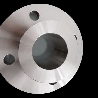
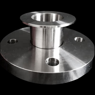
STUB ENDS TYPICAL APPLICATIONS
The combination of stub ends and backing flanges is an alternative way to join pipes compared to the use of standard flanges. This solution is used in these typical scenarios:
- Applications where rotating back flanges are preferred (to facilitate bolting)
- Pipelines in costly materials, as stainless steel, duplex, super-austenitic (example 6Mo), nickel alloy, titanium and zirconium: indeed, the use of stub ends for this type of pipelines helps End-Users and EPC Contractors reduce the total weight of the flanged joints and their total cost (example: in a stainless steel pipeline, carbon steel backing flanges can be used instead of standard stainless steel flanges – as they do not get in contact with the fluid conveyed by the pipeline – “unwetted materials”)
- High pressure pipelines
TYPES OF STUB ENDS
Stub ends are manufactured in three different types and two standard lenghts
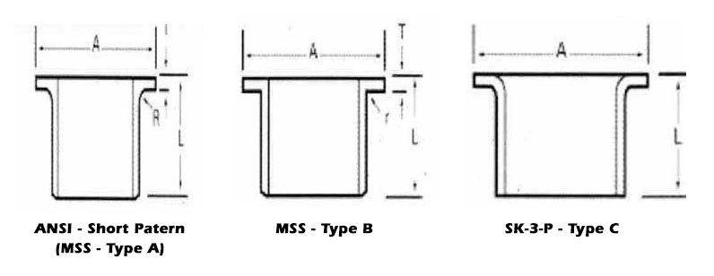
- Type “A”: this type is produced and machined to fit lap joint flanges.The mating surfaces of the stub end and the lap joint flange have a matching profile and surface. The lap thickness of type A stub ends is > = the minimum wall thickness of the connected pipe. The outside the stub end and the lap joint flange have a matching profile and surface. The lap thickness of type A stub ends is > = the minimum wall thickness of the connected pipe. The outside corner of type A has a radius to accommodate the lap join flange, whereas the inside corner is squared.
- Type “B”: this type of stub ends is suited for standard slip-on flanges acting as lap-joint flanges. The lap thickness of type B stub ends is >= the minimum WT of the connecting pipe. The lap of these type of stub ends has generally a serrated face. To ensure tight joints, chamfers on the ID side of the flange are required.
- Type “C”: this last type can be used both with lap joint and slip-on backing flanges and are fabricated out of pipes. The lap of C-type stub ends is flared over and the lap thickness is 75% of the connecting pipe WT. Type C has a short fillet outer radius able to host any back up flange.
- Type “CS”: this type is similar to “C” with the difference that the lap face has concentric serrations machined during the manufacturing process.
Stub Ends dimensions and weight
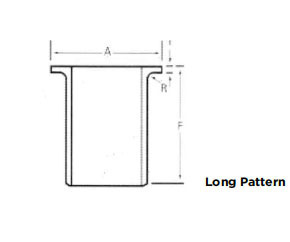
Dimensions and manufacturing tolerances are covered in ASME B16.9 - Butt Weld Fittings and MSS-SP-43 (JIS B2312, JIS B2313 may also apply). Stub End come in three standard lengths, MSS SP43 or ANSI B16.9 short and long pattern. Short pattern stub ends are mostly used for flanges from class 300 to class 600 and above. Besides these standard types, End-Users and contractors can require stub ends with non-standard lengths to suit specific project’s requirement. This will of course come at an additional cost.


ASME B16.9 Stub Ends Long Pattern
|
SCHEDULE STD |
||||||
|
NPS |
A |
T |
G |
F |
R |
KG |
|
1/2 |
21.3 |
2.77 |
34.9 |
76.2 |
3.18 |
0.16 |
|
3/4 |
26.7 |
2.87 |
42.9 |
76.2 |
3.18 |
0.23 |
|
1 |
33.4 |
3.38 |
50.8 |
101.6 |
3.18 |
0.29 |
|
1 1/4 |
42.2 |
3.56 |
63.5 |
101.6 |
4.76 |
0.45 |
|
1 1/2 |
48.3 |
3.68 |
73 |
101.6 |
6.35 |
0.54 |
|
2 |
60.3 |
3.91 |
92.1 |
152.4 |
7.94 |
1 |
|
2 1/2 |
73 |
5.16 |
104.8 |
152.4 |
7.94 |
1.5 |
|
3 |
88.9 |
5.49 |
127 |
152.4 |
9.53 |
2.1 |
|
3 1/2 |
101.6 |
5.74 |
139.7 |
152.4 |
9.53 |
2.5 |
|
4 |
114.3 |
6.02 |
157.2 |
152.4 |
11.11 |
3 |
|
5 |
141.3 |
6.55 |
185.7 |
203.2 |
11.11 |
5.4 |
|
6 |
168.3 |
7.11 |
215.9 |
203.2 |
12.7 |
7.3 |
|
8 |
219.1 |
8.18 |
269.9 |
203.2 |
12.7 |
11.6 |
|
10 |
273.1 |
9.27 |
323.9 |
254 |
12.7 |
18 |
|
12 |
323.9 |
9.53 |
381 |
254 |
12.7 |
21 |
|
14 |
355.6 |
9.53 |
412.8 |
304.8 |
12.7 |
28 |
|
16 |
406.4 |
9.53 |
469.9 |
304.8 |
12.7 |
34 |
|
18 |
457.2 |
9.53 |
533.4 |
304.8 |
12.7 |
39 |
|
20 |
508 |
9.53 |
584.2 |
304.8 |
12.7 |
44 |
|
24 |
609.6 |
9.53 |
692.2 |
304.8 |
12.7 |
57 |
|
SCHEDULE XS |
||||||
|
NPS |
OD |
T |
G |
F |
R |
KG |
|
1/2 |
21.3 |
3.73 |
34.9 |
76.2 |
3.18 |
0.2 |
|
3/4 |
26.7 |
3.91 |
42.9 |
76.2 |
3.18 |
0.3 |
|
1 |
33.4 |
4.55 |
50.8 |
101.6 |
3.18 |
0.4 |
|
1 1/4 |
42.2 |
4.85 |
63.5 |
101.6 |
4.76 |
0.6 |
|
1 1/2 |
48.3 |
5.08 |
73 |
101.6 |
6.35 |
0.7 |
|
2 |
60.3 |
5.54 |
92.1 |
152.4 |
7.94 |
1.4 |
|
2 1/2 |
73 |
7.01 |
104.8 |
152.4 |
7.94 |
2 |
|
3 |
88.9 |
7.62 |
127 |
152.4 |
9.53 |
2.9 |
|
3 1/2 |
101.6 |
8.08 |
139.7 |
152.4 |
9.53 |
3.4 |
|
4 |
114.3 |
8.56 |
157.2 |
152.4 |
11.11 |
4.1 |
|
5 |
141.3 |
9.53 |
185.7 |
203.2 |
11.11 |
7.5 |
|
6 |
168.3 |
10.97 |
215.9 |
203.2 |
12.7 |
10 |
|
8 |
219.1 |
12.7 |
269.9 |
203.2 |
12.7 |
16 |
|
10 |
273.1 |
12.7 |
323.9 |
254 |
12.7 |
24 |
|
12 |
323.9 |
12.7 |
381 |
254 |
12.7 |
29 |
|
14 |
355.6 |
12.7 |
412.8 |
304.8 |
12.7 |
38 |
|
16 |
406.4 |
12.7 |
469.9 |
304.8 |
12.7 |
43 |
|
18 |
457.2 |
12.7 |
533.4 |
304.8 |
12.7 |
49 |
|
20 |
508 |
12.7 |
584.2 |
304.8 |
12.7 |
63 |
|
24 |
609.6 |
12.7 |
692.2 |
304.8 |
12.7 |
76 |
|
DIMENSIONAL TOLERANCES ASME B16.9 (in mm) |
||||||
|
NPS |
1/2 - 1 1/2 |
3 - 3 1/2 |
4 |
5 - 8 |
10 - 18 |
20 - 24 |
|
Outside diameter (OD) |
1.6 |
1.6 |
1.6 |
2.29 |
4.06 |
6.35 |
|
0.8 |
-1.6 |
-3.05 |
-4.83 |
|||
|
Overall lenght (F) |
1.6 |
1.6 |
1.6 |
1.6 |
2 |
2 |
|
Outer lap diameter (G) |
0 |
0 |
0 |
0 |
0 |
0 |
|
-0.76 |
-0.76 |
-0.76 |
-0.76 |
-1.6 |
-1.6 |
|
|
Lap thk (T) |
1.52 |
1.52 |
1.52 |
1.52 |
1.52 |
1.52 |
|
0 |
0 |
0 |
0 |
0 |
0 |
|
|
Fillet lap radius (R) |
0 |
0 |
0 |
0 |
0 |
0 |
|
-0.76 |
-0.76 |
-1.6 |
-1.6 |
-1.6 |
-1.6 |
|
|
WT (t) |
> = 87.5% of NPS |
|||||
MSS SP-43 Stub Ends

|
SCHEDULE 10S |
||||||
|
NPS |
OD |
T |
G |
F |
R |
KG |
|
1/2 |
21.3 |
2.11 |
34.9 |
50.8 |
3.18 |
0.07 |
|
3/4 |
26.7 |
2.11 |
42.9 |
50.8 |
3.18 |
0.1 |
|
1 |
33.4 |
2.77 |
50.8 |
50.8 |
3.18 |
0.16 |
|
1 1/4 |
42.2 |
2.77 |
63.5 |
50.8 |
4.76 |
0.22 |
|
1 1/2 |
48.3 |
2.77 |
73 |
50.8 |
6.35 |
0.25 |
|
2 |
60.3 |
2.77 |
92.1 |
63.5 |
7.94 |
0.43 |
|
2 1/2 |
73 |
3.05 |
104.8 |
63.5 |
7.94 |
0.57 |
|
3 |
88.9 |
3.05 |
127 |
63.5 |
9.53 |
0.73 |
|
4 |
114.3 |
3.05 |
157.2 |
76.2 |
11.11 |
1.09 |
|
5 |
141.3 |
3.4 |
185.7 |
76.2 |
11.11 |
1.47 |
|
6 |
168.3 |
3.4 |
215.9 |
88.9 |
12.7 |
2.15 |
|
8 |
219.1 |
3.76 |
269.9 |
101.6 |
12.7 |
3.22 |
|
10 |
273.1 |
4.19 |
323.9 |
127 |
12.7 |
5.13 |
|
12 |
323.9 |
4.57 |
381 |
152.4 |
12.7 |
8.16 |
|
14 |
355.6 |
4.78 |
412.8 |
152.4 |
12.7 |
10.89 |
|
16 |
406.4 |
4.78 |
469.9 |
152.4 |
12.7 |
12.7 |
|
18 |
457.2 |
4.78 |
533.4 |
152.4 |
12.7 |
17.24 |
|
20 |
508 |
5.54 |
584.2 |
152.4 |
12.7 |
21.77 |
|
24 |
609.6 |
6.35 |
692.2 |
152.4 |
12.7 |
27.22 |
|
SCHEDULE 40S |
||||||
|
NPS |
OD |
T |
G |
F |
R |
KG |
|
1/2 |
21.3 |
2.77 |
34.9 |
50.8 |
3.18 |
0.09 |
|
3/4 |
26.7 |
2.87 |
42.9 |
50.8 |
3.18 |
0.12 |
|
1 |
33.4 |
3.38 |
50.8 |
50.8 |
3.18 |
0.17 |
|
1 1/4 |
42.2 |
3.56 |
63.5 |
50.8 |
4.76 |
0.25 |
|
1 1/2 |
48.3 |
3.68 |
73 |
50.8 |
6.35 |
0.31 |
|
2 |
60.3 |
3.91 |
92.1 |
63.5 |
7.94 |
0.61 |
|
2 1/2 |
73 |
5.16 |
104.8 |
63.5 |
7.94 |
0.8 |
|
3 |
88.9 |
5.49 |
127 |
63.5 |
9.53 |
1.13 |
|
4 |
114.3 |
6.02 |
157.2 |
76.2 |
11.11 |
1.87 |
|
5 |
141.3 |
6.55 |
185.7 |
76.2 |
11.11 |
2.28 |
|
6 |
168.3 |
7.11 |
215.9 |
88.9 |
12.7 |
3.57 |
|
8 |
219.1 |
8.18 |
269.9 |
101.6 |
12.7 |
6.07 |
|
10 |
273.1 |
9.27 |
323.9 |
127 |
12.7 |
10.07 |
|
12 |
323.9 |
9.53 |
381 |
152.4 |
12.7 |
14.29 |
Ends/Face lap finishing
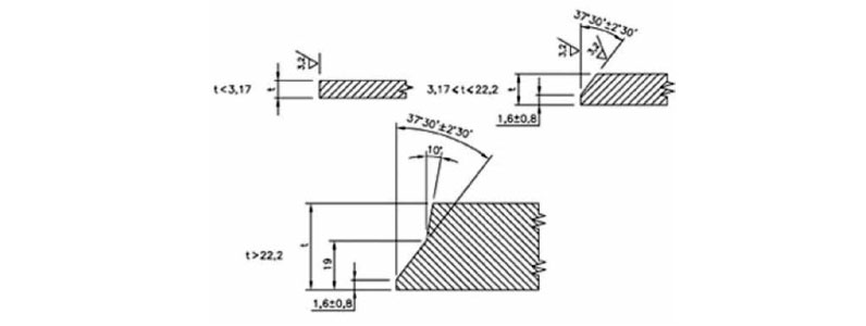
The following types of ends may be ordered:
- Beveled Ends (generally ASME B16.25)
- Squared Ends
- Flanged Ends
- Victaulic Grooves
- Threaded Ends (Male Only)
Material for Stub Ends
Stub Ends are available in numerous ASTM and other international recognized materials, to match pipe specifications, as low alloy, stainless steel, austenitic-ferritic, high alloy steels (nickel alloy such as Inconel, Incoloy 800, Monel, Hastelloy C276), non-ferrous materials (copper, cupronickel 90 /10 and cupronickel 70 / 30) and titanium / zirconium / tantalum.
Lap-joint flanges are most commonly available in carbon steel and low temperature carbon steel, because it is a lower cost than the Stub End that will be wetted by the service and it must be of a suitable grade of steel. If orientation and alignment of bolt holes is the only issue, then for standardization, then the Stub End and the Lap Joint Flange can be of the same material.
The most common material grade for stub end is the ASTM A403 / ASME SA403 (stainless steel stub ends). With reference to EU materials, the most common grades are DIN 1.4301, DIN1.4306, DIN 1.4401, DIN 1.4404
Stub Ends assembly
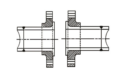
Stub ends and lap joint flanges can be assembled following this process:
- The Lap Flange is slipped over and onto the Stub end Flange.
- The Stub End Flange is then welded onto a pipe spool, using an approved Welding. Procedure Specification (WPS), by a qualified Welder. The Lap Joint Flange, backing Flange, can revolve around the Stub End, which is now attached to the piping spool.
- The bolt holes of the Lap Joint Flange can now be orientated and aligned with the bolt holes of a mating Flange of the same ASME designate rating and NPS.
The Lap Joint Flange can be mated to any Flange covered in ASME B16.5, Weld Neck, Slip On, Threaded, Socket Weld, another Lap Joint Flange. It can also be mated to a fabricated plate Flange with compatible, bolting dimensions.
Why use Stub Ends?
Commercial benefits
Commercial advantages are that the Stub End, will be wetted and it must be made of a grade of material that meets the process design and service conditions of the pipeline. However, the Lap Flange is un-wetted and it can be made of a lower grade of material as long as it meets
the mechanical strength requirements of the piping systems.
This means that instead of:
- Duplex Stub End and a Duplex Lap Joint, you could have Duplex Stub End and Carbon Steel Lap Flange.
- Or you could have Stainless Stub End and Carbon Steel Lap Flange. There are other bimetallic combinations that result in a flange assembly that is commercially cheaper.
During recent years the price differential between Duplex/Stainless Steel and Carbon Steel has narrowed and this practice on large Projects has become less common, however a cost difference always exists (the higher the NPS and the length of the pipeline / piping system, the higher the saving). On the other hand, the warehousing cost of one single component, i.e. a Weld Neck Flange, requires less shelf space than the cost of warehousing a Lap Joint and a Stub End. End Users and Contractors shall determine the actual convenience of using stub ends, considering all these factors and generally the commercial advantage is still valid and it may suit certain situation, especially in “brownfield” modifications.
Installation benefits
The “loose” Flange concept of a Lap Joint, is very beneficial during field installation of piping systems. If two spools are to be mated up in the field, having one Flange that can be rotated is very advantageous when aligning the bolt holes, prior to the introduction of the Stub bolt and the accompanying nuts. The facility of easier orientation and alignment of bolt holes, is of particular use it there is a spool that
has to be removed frequently, if positive isolation is a process requirement.

Stub Ends limitations
A Lap Joint consists of two independent components that are not integrated with a weld and like for like in size/pressure class/material it lacks the mechanical strength and capabilities to withstand fatigue, like a one piece Weld Neck Flange or a welded together Slip On or Socket Weld Flanges. In cyclic services, collars EN 1092-1 type 35 PN 16-25-40 are used instead of stub ends (especially to close pumps and compressors). If carefully consideration is given to Process Design condition, the service and the final application, then a Lap Joint Flange mechanical connection are a valid and cheaper method for installing piping systems compared to the use of standard flanges.
How to order a Stub Ends
The following information shall be provided to order a stub end:
- NPS
- Schedule
- Length (according to norms MSS SP43 / ASME B16.9 / custom)
- Specs and material grade
- Ends finish
- Execution: seamless / welded (wx)
Why Nuova Rid?
- Manufacturing Range: up to 48” Seamless / Welded hot formed
- Welded Stub Ends obtained by hot forming process starting from welded and 100% X Rayed Pipes
- The stub end is produced with only 1 longitudinal seam: no additional weld for the fitting construction. No welded execution of plate ring on pipe by circumferential weld and no build up construction = seamless execution with joint efficiency ”E”=1 (as per ASME B 31.3 Table 302.3.4 Point 3B Double Butt Weld+100X Ray Examination: Method Used Up To 48” included)


